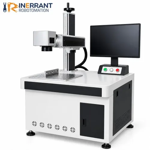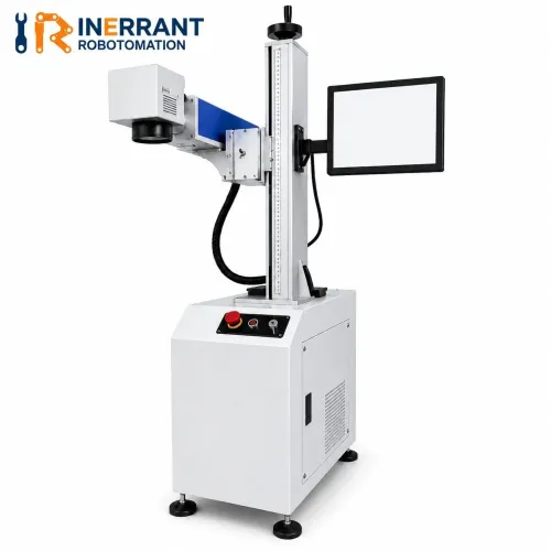
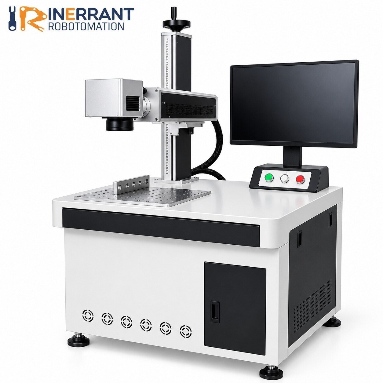
A fiber laser can mark steel, aluminium, brass and many engineered materials quickly, but its suitability depends on the mark process, surface finish, optics, fixture and line interface—not the wattage on the nameplate. By the end, you will be able to compare laser types, estimate production fit and identify the tests and documentation a supplier must provide before installation.
Key takeaways
- Confirm the metal grade, coating and mark type before selecting laser power.
- Choose the lens field size from the largest required mark and working distance.
- Calculate cycle time, loading time and reject handling against line takt time.
- Approve the supplier only after testing contrast, durability and readability on your parts.
What a Fiber Laser Does Differently on a Factory Line
A fiber laser marking machine for factory production lines usually uses near-infrared light at about 1,060–1,080 nm. It marks steel, stainless steel, aluminium, copper, brass and other metals without contact, but absorption on plastic, glass and ceramic depends on the exact grade and finish.
Fixture accuracy matters too: poor seating can shift the mark more than the scanner’s stated resolution.
| Option | Wavelength and suitable materials | Mark, heat and depth | Factory implications |
|---|---|---|---|
| Standard pulsed fiber | 1,060–1,080 nm; most metals | High-contrast anneal or etch; low to moderate depth; small heat-affected area | Fast, low maintenance, long source life and moderate operating cost |
| MOPA fiber | Usually 1,060–1,080 nm; metals and selected anodised parts | Adjustable pulses enable black anodised-aluminium marks, stainless colour and lower heat input | Higher control and cost; not automatically faster |
| CO2 | 9.3 or 10.6 µm; plastics, rubber, wood, glass and coated materials | Strong surface contrast; limited metal marking; broader heat effect | Tube, mirror and gas maintenance; long-established but slower for many metals |
| UV | About 355 nm; plastics, glass, ceramics and delicate coatings | Fine, high-contrast marks with very low heat transfer | Higher equipment cost; source replacement is costly |
| Electromagnetic dot-peen | No optical wavelength; ferrous and non-ferrous metals | Indented, deep, durable dots; mechanical deformation | Slower and noisier, with stylus wear; no laser extraction system |
An industrial fiber laser marker still needs replaceable protective windows, accessible filters, recipe backups, event logs and recovery after power loss. Compare machines using your parts: request mark time, passes, pulse settings, field size, contrast, depth, colour and durability results. A polished supplier coupon proves little.
Choose the Mark Process, Power and Material Before the Machine
A standard pulsed fiber laser is sufficient for most steel, stainless steel, aluminium, copper, brass and other engineered-metal part numbers, barcodes and shallow logos. The usual 20–50 W source suits routine fiber laser marking for factory parts when the required result is contrast, not substantial material removal.
| Option | Best material or result | Choose it when |
|---|---|---|
| Standard pulsed fiber, 20–50 W | Metals; annealing, etching and shallow engraving | You need fast, durable identification on untreated or coated metal |
| MOPA fiber, 20–60 W | Anodised aluminium, sensitive plastics and colour marks | Pulse width control must limit melting, whitening or heat tint |
| UV, 3–15 W | Plastics, glass, ceramics and delicate coated parts | A small heat-affected zone and photochemical surface change matter |
| CO2, 30–100 W | Rubber, wood, cardboard, acrylic and other organics | The material absorbs longer-wavelength infrared energy better |
| Deep-marking fiber, 50–100 W or higher | Steel tools, dies and exposed metal surfaces | The mark must survive machining, abrasion or repeated cleaning |
Power does not guarantee a better mark. Excess energy can warp plastic, burn lubricant or widen a barcode; insufficient energy extends cycle time through extra passes.
Ask for a report made on your exact grade and finish showing mark time, passes, field size, pulse settings, contrast, depth or colour, and durability after the required cleaning or abrasion test.
Specify fume extraction when marking paint, plating, oil, polymers or contaminated surfaces. General room ventilation does not control the resulting plume.
Match the Lens, Field Size and Layout to the Part
Choose the smallest scan field that covers the complete mark. A 70 × 70 mm field preserves finer detail than a 175 × 175 mm field when the same optical configuration is used, because the larger field generally produces a larger spot and lower energy density.
Compare nominal spot size, minimum line width and edge quality, not field size alone.
Set the focal distance as a production dimension. Confirm that the lens working distance leaves room for loading, guarding and part access. Cast surfaces, weld distortion and height variation require a controlled datum, height-adjustable Z axis, 3D focusing or a part-present sensor; otherwise line width and contrast change across the batch.
- Seat every part against the same primary datum.
- Control rotation and marking-surface height.
- Leave clearance across the entire scan field.
- Prevent polished surfaces from directing radiation toward the operator or viewing aperture.
| Layout | Best fit | Cost or risk |
|---|---|---|
| Fixed galvanometer head | One defined face and fast repeat cycles | Limited access outside its field |
| XY or traversing head | Large parts or multiple marking positions | Adds motion time and positional-error sources |
| Rotary axis or fixture | Cylindrical parts or indexed faces | Adds setup complexity and maintenance |
Ask for a sample-mark report on your actual material and finish, listing mark time, passes, field size, pulse settings, contrast, depth or colour, and durability after processing.
Calculate Whether the Marker Fits Your Production Line
Real cycle time is the time from part arrival to accepted-part release, not the laser’s advertised scan speed. Calculate it against takt time using the complete sequence.
- Loading and seating the part, including fixture clamping and datum confirmation
- Conveyor stop, part detection, or robot handoff
- Focusing, scan-head acceleration and deceleration, and axis travel
- Marking passes, hatch spacing, line density, and required contrast
- Vision inspection, PLC handshakes, cooling, settling, and result logging
- Reject transfer, chute clearance, rework routing, and fault recovery
A fixed-head industrial fiber laser marker is fast inside a defined field. A traversing XY or rotary axis reaches larger parts or multiple faces, but adds motion, positional-accuracy checks, and maintenance. Include those movements in the cycle rather than comparing scanner speeds.
Part dimensions alone do not determine fit. Map the marking window’s position relative to the conveyor datum, confirm clearance around reflective surfaces, and ensure the fixture controls seating and rotation.
A nominally high-resolution fiber laser marking machine for factory production lines will still produce variable codes if the part rocks or arrives outside the focal plane.
For line integration, define machine-ready, cycle-start, marking-busy, cycle-complete, fault, and safety-status signals. Also specify what happens after a missing part, duplicate trigger, communication timeout, or conveyor stop. Compare the calculated cycle time with takt time after inspection and rejection handling; a stand-alone marker that misses either requirement is not line-ready.
Supplier speed figures count only when material, mark size, fill pattern, contrast, and pass count match your parts.
Test the Supplier on Your Parts Before You Approve the Purchase
A supplier’s polished stainless-steel coupon proves little. Give every shortlisted fiber laser marking machine manufacturer your actual parts, coating, geometry and production fixture, then require results from the same datum and loading method used on the line.
1. Request a sample-mark report stating mark time, number of passes, lens and field size, pulse settings, power, frequency, speed, contrast, depth or colour result, and readability after abrasion, solvents, heat or corrosion exposure. Reject a report based only on supplier coupons.
2. Check the fixture, not just the laser resolution. It must control seating, rotation and marking height, leave scan-field clearance, and stop reflective surfaces directing radiation toward the operator or viewing window.
3. Obtain the enclosure’s laser classification, IEC 60825-1 compliance evidence, ISO 11553-1 risk assessment, interlock and viewing-window specifications, emergency-stop circuit details, user manual and maintenance instructions. Confirm that doors and loading apertures cannot expose the internal Class 4 beam.
4. Put service terms in writing: response time in Pune, remote-support hours, stocked protective windows and filters, spare scanner or source access, parameter backup, password-controlled recipes, event logs, recovery after power or network loss, and documented alignment procedures.
Ask whether the supplier can complete the PLC, conveyor, press-line, barcode, inspection and reject-bin interfaces. A quote for a fiber laser marking machine in Pune is not evidence of integration capability; verify wiring drawings, software ownership and commissioning responsibility. Inerrant belongs on the shortlist only after it demonstrates those capabilities on your parts.
Related products
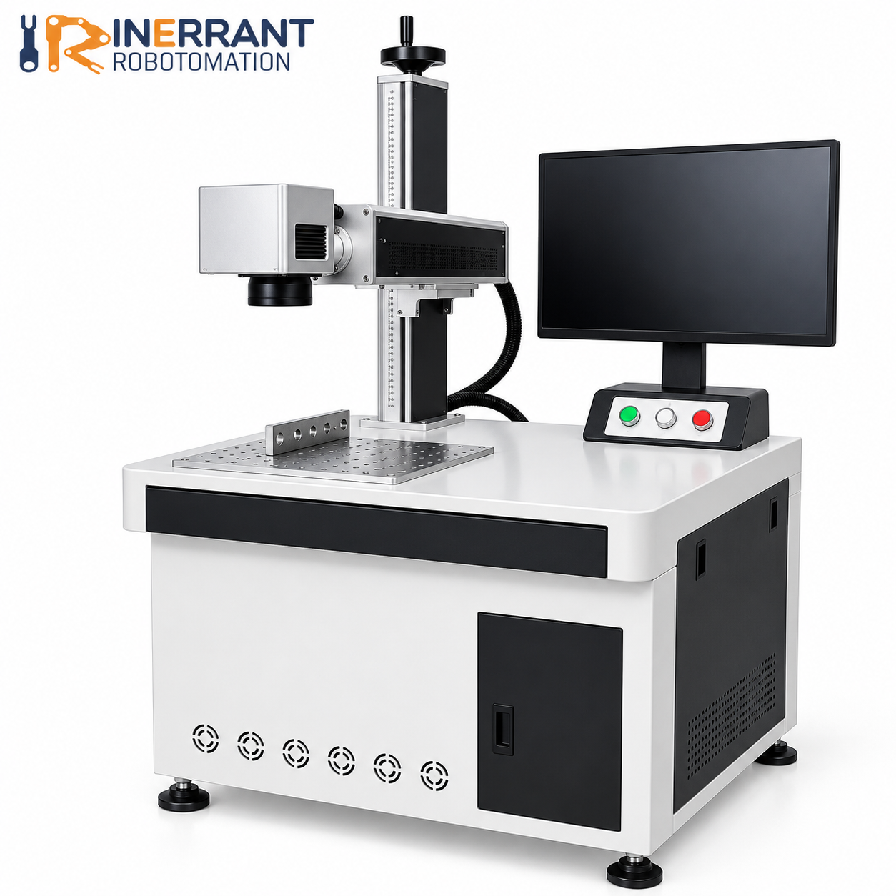 | Laser Marking Machine Inerrant Robotomation Pvt. Ltd is a leading Manufacturer and Supplier of Laser Marking Machine from Pune, Maharashtra, India. View product → |
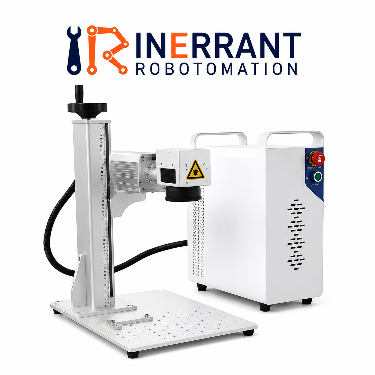 | Laser Marking Machine Inerrant Robotomation Pvt. Ltd. announces the MOPA Laser Marking Machine, which is highly accurate and adaptable for numerous materials. View product → |
Frequently asked questions
What does a fiber laser do differently on a factory production line?
It marks parts without contact, tooling wear or ink, using near-infrared light around 1,060–1,080 nm. It suits many metals, while plastic, glass and ceramic results depend on the material grade and finish.
How do you choose fiber laser power and the marking process?
Start with the part material, coating and required result: annealing, engraving, etching or colour change. Test those conditions before choosing power, speed and frequency.
How do lens field size and machine layout affect the choice?
Select a lens that covers the largest required mark while preserving the needed resolution. Check working distance, part access, guarding, conveyor position and operator loading space.
How can you calculate whether a marker fits your production line?
Compare marking time plus loading, unloading, inspection and communication delays with the line takt time. Include changeovers, rejects, maintenance access and the required buffer.
What should you test before approving a fiber laser marking supplier?
Run production parts through the proposed machine and verify contrast, depth, code readability, durability, cycle time, repeatability and integration with your controls.