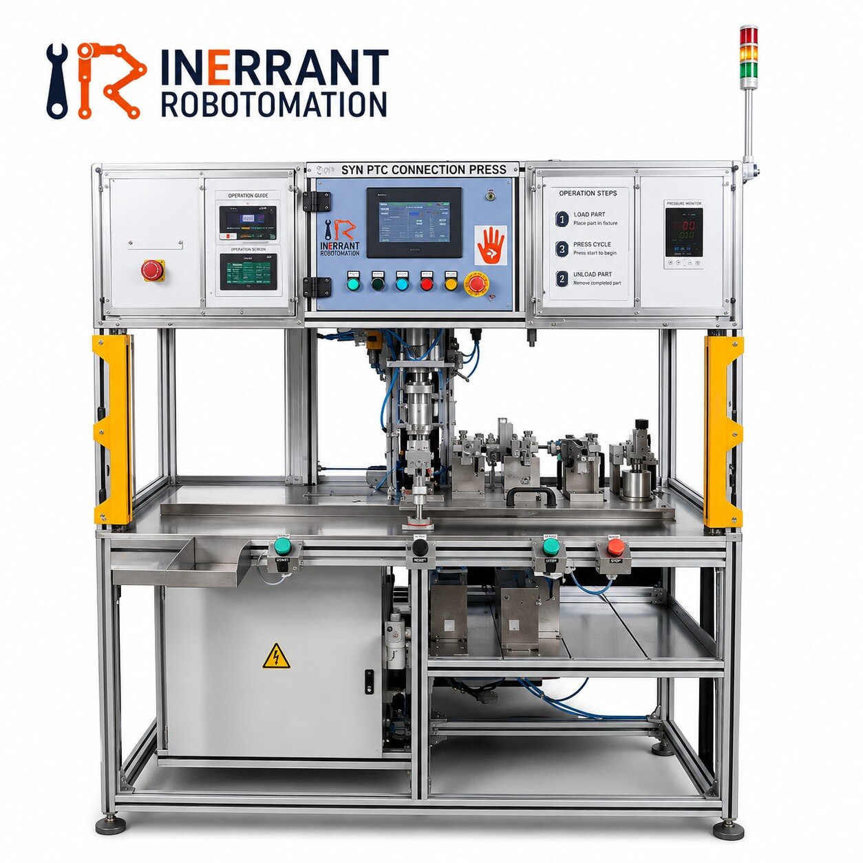
A pneumatic press is only as capable as the force that reaches the tool, the frame that supports the load and the air circuit that supplies it. By the end, you will be able to calculate usable force, compare press constructions, specify the working envelope and reject a machine that cannot meet your process, safety or duty-cycle requirements.
Key takeaways
- Calculate force from inlet pressure and cylinder bore, then allow for losses.
- Specify daylight, stroke, throat depth, cycle time, and required repeatability.
- Match the frame and guidance system to side loads and tooling accuracy.
- Choose another press type when force, dwell, or energy demands exceed pneumatics.
How Much Force Will the Pneumatic Cylinder Actually Deliver?
At 6 bar, a 50 mm-bore cylinder produces about 1.18 kN, or 120 kgf, on its extend stroke before losses. Calculate it as F = p × πD²/4, using pressure at the cylinder inlet and bore D. A pneumatic press machine rated only as “120 kg” hides whether that figure is theoretical or usable.
Stroke does not multiply force. It determines how far the ram travels, whether the tool reaches the workpiece, and how much air each cycle consumes. Doubling stroke roughly doubles extend-and-retract air volume; doubling cycle rate roughly doubles consumption. The retract force is lower because the rod occupies part of the piston area.
Use the pressure available during the working part of the stroke, not the compressor’s nameplate setting. A plant supply of 6–7 bar can fall at the cylinder when a regulator, valve, tubing or muffler restricts flow during a fast movement. Specify pressure at the inlet, bore, stroke direction, speed and cycle rate.
Usable tool force is lower than maximum cylinder force. Deduct cylinder and guide friction, pressure drop, misalignment and linkage losses, then apply a safety margin to the required forming, staking or punching load. A toggle or cam changes force with position, so bore alone cannot predict output; request a force-versus-position figure at the tool.
For an industrial press machine, require the supplier to state maximum force and continuous usable force separately, with the force point identified. If the cylinder rod carries side load instead of a guided ram or die set, wear and seal damage can reduce repeatable force long before the cylinder reaches its calculated rating.
Which Press Dimensions and Cycle Details Belong in the Specification?
A table size alone cannot prove that a die will fit. A quotation for an industrial press machine for pneumatic press work must separate the dimensions that determine reach, clearance, alignment and mounting.
| Item | Put in the specification | Failure if omitted |
|---|---|---|
| Stroke | Usable ram travel, in millimetres | The tool may not complete its forming or punching action |
| Maximum daylight | Open height from bed to ram | The die may not enter the press |
| Shut or closed height | Ram-to-bed height at full closure | The tool may bottom out before reaching the work |
| Throat depth | Bed edge to ram centreline | Deep parts may not reach the force point |
| Bed dimensions | Length and width of the working surface | The die may overhang or clash with the frame |
| Ram dimensions | Face size, travel and mounting pattern | The upper tool may not attach securely |
| Die mounting | T-slots, tapped holes, bolster plate and locating features | Alignment becomes improvised and repeatability suffers |
Specify the production cycle separately from the mechanical envelope:
- Strokes per minute, including acceleration and return time
- Dwell time at bottom dead centre
- Required cycle time and annual operating hours
- Allowable continuous force and peak force
- Loading and unloading time, including operator access
- Tool change clearance and adjustment range
State the force point and the load direction too. A quoted tonnage for an industrial press machine has little value if the supplier does not identify where the load acts and whether the figure applies continuously or only at the end of the stroke.
Specify guided-ram, die-set or external-guide provisions separately; the cylinder rod is not a lateral-load guide.
Which Frame and Guidance Design Fits the Operation?
Choose the frame by the load path: where the force enters the tool, how far it sits off-centre, and how much access operators need. A cylinder rod supplies motion; it is not a die guide.
| Option | What it provides | When it fits |
|---|---|---|
| C-frame | Three-sided access with a compact, open throat | Centre-loaded punching, riveting, staking and short tooling where occasional access matters more than maximum rigidity |
| H-frame | Box-like structure with stronger resistance to deflection | Off-centre loading, deep tooling, larger workpieces and repeated forming where angular error would scrap parts |
| Guided-cylinder | Cylinder-mounted guide rails or a guided ram that controls the tool | Straight pressing with modest lateral loads, provided the guide is rated for the die and eccentric force |
| Toggle | Linkage that trades stroke speed for high force near the end of travel | Crimping, embossing and assembly operations needing firm end-position pressure; specify force and speed at each toggle position |
| Four-column | Four posts supporting a balanced platen and die set | Large dies, multi-point tooling and loads spread across a wide work area; accept reduced side access and more guarding |
For punching, forming and staking, specify a guided ram, die set or external guide system separately from the pneumatic actuator. Side load on an unguided rod damages its bearing and seal, then shifts punch clearance.
State the permitted eccentric load, lateral load, platen parallelism and deflection at the tool face. A quoted “tonnage” means little without its force point and duty condition; a compact pneumatic press machine with a rigid guide can outperform a larger industrial press machine that bends under an off-centre die.
Can the Air System and Safeguards Support Reliable Production?
A pneumatic press machine is production-ready only when its air supply, motion circuit and guarding work together. A quotation for an industrial press machine for pneumatic press work must state consumption in standard litres per cycle, peak flow and minimum inlet pressure, not just cylinder size.
1. Check the air-preparation train: water separator, 5-micron filter, regulator with gauge, dryer, isolation valve and soft-start dump valve. Confirm the plant compressor can supply peak demand while other equipment runs. Water, pressure sag and an undersized regulator cause slow or incomplete strokes.
2. Ask for the pneumatic press machine’s air consumption at the specified stroke and cycle rate. Include blow-off, ejector and cushioning consumption; these are easy to omit from compressor sizing.
3. Require adjustable meter-out flow controls, a valve sized for the cylinder, end-of-stroke cushioning and a monitored pressure switch. Test acceleration when the die contacts the workpiece, because stored air can make the ram lunge.
4. Verify usable force with a calibrated load cell or force transducer at the actual tooling position and speed. A cylinder pressure gauge alone cannot reveal friction, pressure drop or force loss during a fast stroke. Set an acceptance limit and record calibration evidence.
5. Select point-of-operation protection from a documented risk assessment covering the ram, die, stock and ejector. Use fixed or interlocked guards, presence sensing or two-hand controls where appropriate, anti-repeat logic, emergency stopping, and pneumatic energy isolation with lockout.
Check unexpected restart after air restoration, and confirm whether OSHA 29 CFR 1910.212 or 1910.217 applies to the machine’s jurisdiction and construction.
When Is a Pneumatic Press the Wrong Machine to Buy?
Choose another press when the job demands force, dwell, energy control or production speed that compressed air cannot deliver consistently. Do not select an industrial press machine for pneumatic press work simply because its headline tonnage matches the calculation.
| Option | Choose it when | State in the enquiry |
|---|---|---|
| Hydraulic | You need high force, long dwell, deep forming or force held at the bottom of the stroke | Usable force, pressure, stroke, dwell time, speed and oil temperature range |
| Hydropneumatic | You need a fast approach followed by a powerful, controlled working stroke | Approach speed, intensification ratio, working force, stroke and cycle time |
| Mechanical | You need high-speed repetitive stamping with fixed stroke, timed motion and a flywheel-driven cycle | Tonnage at the force point, strokes per minute, shut height, stroke and die envelope |
| Servo | You need programmable position, speed, force, dwell or ram profiles, including different recipes | Force-position curve, motion profile, accuracy, repeatability and cycle rate |
Turn the choice into a measurable supplier specification. State stroke, maximum daylight, shut height or closed height, throat depth, bed dimensions, ram dimensions and die-mounting provisions as separate figures; “working area” proves none of them.
Give Inerrant, or any competing builder, the same force point, eccentric-load limit, duty cycle, usable force at operating pressure, and tooling details. Also require the supplier to identify the guided ram or external guide system, guarding standard, and the device that prevents ram descent after air loss or restoration.
Related products
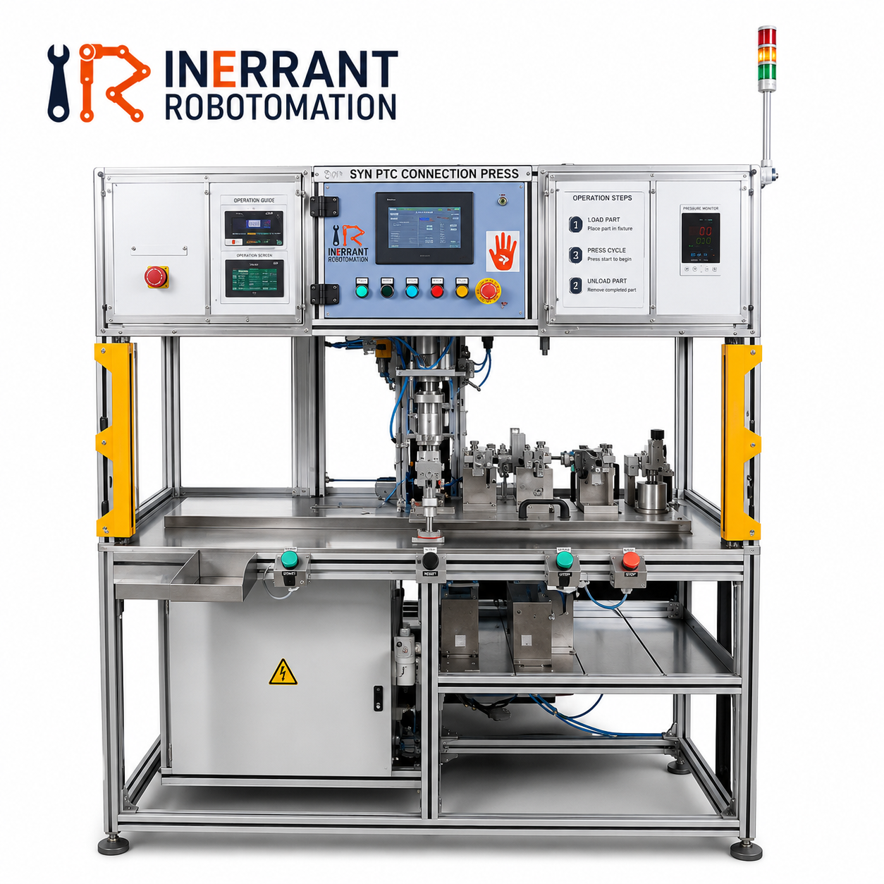 | Press Machine In today’s fast-paced industrial world, automation, speed, and precision are key elements that drive manufacturing excellence. View product → |
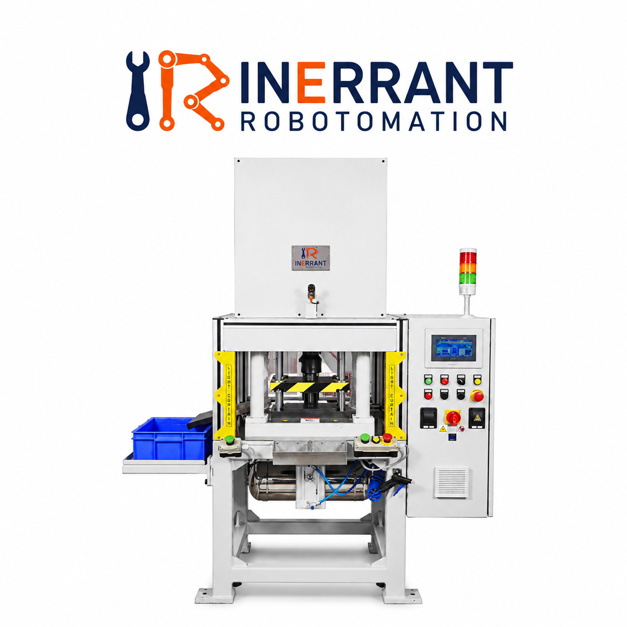 | Press Machine In the modern manufacturing landscape, precision, consistency, and reliability are key factors that drive productivity and quality. View product → |
Frequently asked questions
How do you calculate pneumatic cylinder pressing force?
Use F = p × πD²/4, with pressure at the cylinder inlet and bore D. A 50 mm-bore cylinder at 6 bar produces about 1.18 kN, or 120 kgf, before losses.
Which dimensions belong in a pneumatic press specification?
Specify maximum force, stroke, daylight, throat depth, bed and ram dimensions, tooling space, cycle time, and required repeatability.
What frame and guidance design should you choose?
Choose the frame and guidance arrangement according to tooling alignment, side loads, workpiece size, and the accuracy your process requires.
When is a pneumatic press the wrong machine to buy?
Choose another press type when the process needs very high force, long controlled dwell, precise force-displacement control, or energy beyond the air system's capacity.